segunda-feira, 23 de dezembro de 2013

terça-feira, 7 de fevereiro de 2012
Control Structures goto
goto
Transfers program flow to a labeled point in the programSyntax
label:goto label; // sends program flow to the label
Tip
The use of goto is discouraged in C programming, and some authors of C programming books claim that the goto statement is never necessary, but used judiciously, it can simplify certain programs. The reason that many programmers frown upon the use of goto is that with the unrestrained use of goto statements, it is easy to create a program with undefined program flow, which can never be debugged.With that said, there are instances where a goto statement can come in handy, and simplify coding. One of these situations is to break out of deeply nested for loops, or if logic blocks, on a certain condition.
Example
for(byte r = 0; r < 255; r++){
    for(byte g = 255; g > -1; g--){
        for(byte b = 0; b < 255; b++){
            if (analogRead(0) > 250){ goto bailout;}
            // more statements ...
        }
    }
}
bailout:

References
Control Structures return
return
Terminate a function and return a value from a function to the calling function, if desired.Syntax:
return;return value; // both forms are valid
Parameters
value: any variable or constant typeExamples:
A function to compare a sensor input to a thresholdint checkSensor(){
if (analogRead(0) > 400) {
return 1;
else{
return 0;
}
}
The return keyword is handy to test a section of code without having to "comment out" large sections of possibly buggy code. void loop(){
// brilliant code idea to test here
return;
// the rest of a dysfunctional sketch here
// this code will never be executed
}
See also
commentsReferences
Control Structures continue
continue
The continue statement skips the rest of the current iteration of a loop (do, for, or while). It continues by checking the conditional expression of the loop, and proceeding with any subsequent iterations.Example
for (x = 0; x < 255; x ++)
{
    if (x > 40 && x < 120){      // create jump in values
        continue;
    }

    digitalWrite(PWMpin, x);
    delay(50);
}
References
Control Structures break
break
break is used to exit from a do, for, or while loop, bypassing the normal loop condition. It is also used to exit from a switch statement.Example
for (x = 0; x < 255; x ++)
{
    digitalWrite(PWMpin, x);
    sens = analogRead(sensorPin);
    if (sens > threshold){      // bail out on sensor detect
       x = 0;
       break;
    }
    delay(50);
}

References
Control Structures do... while
do - while
The do loop works in the same manner as the while loop, with the exception that the condition is tested at the end of the loop, so the do loop will always run at least once.do
{
// statement block
} while (test condition);
Example
do
{
  delay(50);          // wait for sensors to stabilize
  x = readSensors();  // check the sensors

} while (x < 100);

References
Control Structures while
while loops
Description
while loops will loop continuously, and infinitely, until the expression inside the parenthesis, () becomes false. Something must change the tested variable, or the while loop will never exit. This could be in your code, such as an incremented variable, or an external condition, such as testing a sensor.Syntax
while(expression){
  // statement(s)
}
Parameters
expression - a (boolean) C statement that evaluates to true or falseExample
var = 0;
while(var < 200){
  // do something repetitive 200 times
  var++;
}

References
Control Structures switch case
switch / case statements
Like if statements, switch...case controls the flow of programs by allowing programmers to specify different code that should be executed in various conditions. In particular, a switch statement compares the value of a variable to the values specified in case statements. When a case statement is found whose value matches that of the variable, the code in that case statement is run.The break keyword exits the switch statement, and is typically used at the end of each case. Without a break statement, the switch statement will continue executing the following expressions ("falling-through") until a break, or the end of the switch statement is reached.
Example
switch (var) {
    case 1:
      //do something when var equals 1
      break;
    case 2:
      //do something when var equals 2
      break;
    default:
      // if nothing else matches, do the default
      // default is optional
  }
Syntax
switch (var) {
  case label:
    // statements
    break;
  case label:
    // statements
    break;
  default:
    // statements
}
Parameters
var: the variable whose value to compare to the various caseslabel: a value to compare the variable to
See also:
if...else Reference HomeReferences
Control Structures for
for statements
Desciption
The for statement is used to repeat a block of statements enclosed in curly braces. An increment counter is usually used to increment and terminate the loop. The for statement is useful for any repetitive operation, and is often used in combination with arrays to operate on collections of data/pins.There are three parts to the for loop header:
for (initialization; condition; increment) { //statement(s); } 
Example
// Dim an LED using a PWM pin
int PWMpin = 10; // LED in series with 470 ohm resistor on pin 10

void setup()
{
  // no setup needed
}

void loop()
{
   for (int i=0; i <= 255; i++){
      analogWrite(PWMpin, i);
      delay(10);
   }
}
Coding Tips
The C for loop is much more flexible than for loops found in some other computer languages, including BASIC. Any or all of the three header elements may be omitted, although the semicolons are required. Also the statements for initialization, condition, and increment can be any valid C statements with unrelated variables, and use any C datatypes including floats. These types of unusual for statements may provide solutions to some rare programming problems.For example, using a multiplication in the increment line will generate a logarithmic progression:
for(int x = 2; x < 100; x = x * 1.5){
println(x);
}
Generates: 2,3,4,6,9,13,19,28,42,63,94 Another example, fade an LED up and down with one for loop:
void loop()
{
   int x = 1;
   for (int i = 0; i > -1; i = i + x){
      analogWrite(PWMpin, i);
      if (i == 255) x = -1;             // switch direction at peak
      delay(10);
   }
}
See also
Control Structures if... else
if / else
if/else allows greater control over the flow of code than the basic if statement, by allowing multiple tests to be grouped together. For example, an analog input could be tested and one action taken if the input was less than 500, and another action taken if the input was 500 or greater. The code would look like this:if (pinFiveInput < 500)
{
// action A
}
else
{
// action B
}
else can proceed another if test, so that multiple, mutually exclusive tests can be run at the same time. Each test will proceed to the next one until a true test is encountered. When a true test is found, its associated block of code is run, and the program then skips to the line following the entire if/else construction. If no test proves to be true, the default else block is executed, if one is present, and sets the default behavior.
Note that an else if block may be used with or without a terminating else block and vice versa. An unlimited number of such else if branches is allowed.
if (pinFiveInput < 500)
{
  // do Thing A
}
else if (pinFiveInput >= 1000)
{
  // do Thing B
}
else
{
  // do Thing C
}
Another way to express branching, mutually exclusive tests, is with the switch case statement. See also:
switch case Reference HomeReferences
Control Structures if
if (conditional) and ==, !=, <, > (comparison operators)
if, which is used in conjunction with a comparison operator, tests whether a certain condition has been reached, such as an input being above a certain number. The format for an if test is: if (someVariable > 50)
{
// do something here
}
The program tests to see if someVariable is greater than 50. If it is, the program takes a particular action. Put another way, if the statement in parentheses is true, the statements inside the brackets are run. If not, the program skips over the code. The brackets may be omitted after an if statement. If this is done, the next line (defined by the semicolon) becomes the only conditional statement.
if (x > 120) digitalWrite(LEDpin, HIGH);

if (x > 120)
digitalWrite(LEDpin, HIGH);

if (x > 120){ digitalWrite(LEDpin, HIGH); }

if (x > 120){
  digitalWrite(LEDpin1, HIGH);
  digitalWrite(LEDpin2, HIGH);
}                                 // all are correct
The statements being evaluated inside the parentheses require the use of one or more operators: Comparison Operators:
x == y (x is equal to y)
 x != y (x is not equal to y)
 x <  y (x is less than y)
 x >  y (x is greater than y)
 x <= y (x is less than or equal to y)
 x >= y (x is greater than or equal to y)
Warning:
Beware of accidentally using the single equal sign (e.g. if (x = 10) ). The single equal sign is the assignment operator, and sets x to 10 (puts the value 10 into the variable x). Instead use the double equal sign (e.g. if (x == 10) ), which is the comparison operator, and tests whether x is equal to 10 or not. The latter statement is only true if x equals 10, but the former statement will always be true. This is because C evaluates the statement
if (x=10) as follows: 10 is assigned to x (remember that the single equal sign is the assignment operator), so x now contains 10. Then the 'if' conditional evaluates 10, which always evaluates to TRUE, since any non-zero number evaluates to TRUE. Consequently, if (x = 10) will always evaluate to TRUE, which is not the desired result when using an 'if' statement. Additionally, the variable x will be set to 10, which is also not a desired action. if can also be part of a branching control structure using the if...else] construction.
References
Language Reference : Structure loop ()
loop()
After creating a setup() function, which initializes and sets the initial values, the loop() function does precisely what its name suggests, and loops consecutively, allowing your program to change and respond. Use it to actively control the Arduino board.Example
int buttonPin = 3;

// setup initializes serial and the button pin
void setup()
{
  beginSerial(9600);
  pinMode(buttonPin, INPUT);
}

// loop checks the button pin each time,
// and will send serial if it is pressed
void loop()
{
  if (digitalRead(buttonPin) == HIGH)
    serialWrite('H');
  else
    serialWrite('L');

  delay(1000);
}
Reference
Language Reference : Structure setup ()
setup()
The setup() function is called when a sketch starts. Use it to initialize variables, pin modes, start using libraries, etc. The setup function will only run once, after each powerup or reset of the Arduino board.Example
int buttonPin = 3;

void setup()
{
  Serial.begin(9600);
  pinMode(buttonPin, INPUT);
}

void loop()
{
  // ...
}
References
sexta-feira, 12 de agosto de 2011
Arduino Interrupts
MsTimer2 is a small and very easy to use library to interface Timer2 with humans. It's called MsTimer2 because it "hardcodes" a resolution of 1 millisecond on timer2.
UPDATED:
- works on ATmega1280 (thanks to Manuel Negri).
- works on ATmega328 (thanks Jerome Despatis).
- works on ATmega48/88/168 and ATmega128/8.
Methods
- MsTimer2::set(unsigned long ms, void (*f)())
- this function sets a time on ms for the overflow. Each overflow, "f" will be called. "f" has to be declared void with no parameters.
- MsTimer2::start()
- enables the interrupt.
- MsTimer2::stop()
- disables the interrupt.
Source code
License: LGPLMsTimer2.zip
Install it on {arduino-path}/hardware/libraries/
Compile Ubuntu 11.04
First , root mode
sudo su
Unzip MsTimer2.zip
unzip MsTimer2.zip
Copy MsTimer2 from /usr/share/arduino/libraries
cp -r MsTimer2.zip /usr/share/arduino/libraries
Ready, examples are already in default,in the ide
Example
// Toggle LED on pin 13 each second #includevoid flash() { static boolean output = HIGH; digitalWrite(13, output); output = !output; } void setup() { pinMode(13, OUTPUT); MsTimer2::set(500, flash); // 500ms period MsTimer2::start(); } void loop() { }
Bugs
send any bug to javiervalencia80 [at] gmail.comReferences
quinta-feira, 1 de abril de 2010
PAPERduino’s design
2009 05 06
PAPERduino’s design
This is a fully functional version of the Arduino. We eliminated the PCB and use paper and cardboard as support and the result is.. the PAPERduino :D
This is the the first version of the layout design, next we will try more designs, and another materials. You just need to print the top and the bottom layout, and glue them to any kind of support you want. We hope that you start making your own boards. If you do, please share your photos with us, we would love to see them ;)
There is no USB direct connection, so to program the paperduino you will need some kind of FTDI cable or adapter. One of this products will be fine:
FTDI cable from Adafruit Industries
FTDI adapter from Sparkfun

Download PDF
Components list:
1 x 7805 Voltage regulator
2 x LEDs (different colors)
2 x 560 Ohm resistors (between 220oHm and 1K)
1 x 10k Ohm resistor
2 x 100 uF capacitors
1x 16 MHz clock crystal
2 x 22 pF capacitors
1 x 0.01 uF capacitor
1 x button
1 x Atmel ATMega168
1 x socket 28 pin
Female and Male headers


Instructions:
Use a needle to puncture the holes for your components.

Don’t rush, place one component after another and do all the solder work carefully.

Follow the connection lines.

And this should be the final look of your paperduino connections.
PAPERduino for ALL
http://www.google.com/search?client=opera&rls=en&q=paperduino&sourceid=opera&ie=utf-8&oe=utf-8
http://blog.makezine.com/archive/2009/05/paperduino.html?CMP=OTC-0D6B489…
http://gizmodo.com/5248824/paperduino-combines-circuit-boards-with-paint…
http://dailydiy.com/2009/05/11/paperduino/
http://www.freeduino.org/index.html (with 2 stars)
http://search.twitter.com/search?q=paperduino
http://www.engadget.com/2009/05/11/paperduino-is-like-the-cardboard-fort-version-of-every-hackers/
and more..
http://theawesomer.com/paperduino/13281/
http://es.makezine.com/archive/2009/05/paperduino_el_arduino_de_papel.html
http://jmsarduino.blogspot.com/2009/05/paperduino-hifiduino.html
fonte :http://lab.guilhermemartins.net/paperduino-prints/
tags : Arduino, PaperDuino, Pedro Ernesto Scotton, Pedro Scotton, Starter Arduino
This is the the first version of the layout design, next we will try more designs, and another materials. You just need to print the top and the bottom layout, and glue them to any kind of support you want. We hope that you start making your own boards. If you do, please share your photos with us, we would love to see them ;)
There is no USB direct connection, so to program the paperduino you will need some kind of FTDI cable or adapter. One of this products will be fine:
FTDI cable from Adafruit Industries
FTDI adapter from Sparkfun
Download PDF
Components list:
1 x 7805 Voltage regulator
2 x LEDs (different colors)
2 x 560 Ohm resistors (between 220oHm and 1K)
1 x 10k Ohm resistor
2 x 100 uF capacitors
1x 16 MHz clock crystal
2 x 22 pF capacitors
1 x 0.01 uF capacitor
1 x button
1 x Atmel ATMega168
1 x socket 28 pin
Female and Male headers
Instructions:
Use a needle to puncture the holes for your components.
Don’t rush, place one component after another and do all the solder work carefully.
Follow the connection lines.
And this should be the final look of your paperduino connections.
PAPERduino for ALL
http://www.google.com/search?client=opera&rls=en&q=paperduino&sourceid=opera&ie=utf-8&oe=utf-8
http://blog.makezine.com/archive/2009/05/paperduino.html?CMP=OTC-0D6B489…
http://gizmodo.com/5248824/paperduino-combines-circuit-boards-with-paint…
http://dailydiy.com/2009/05/11/paperduino/
http://www.freeduino.org/index.html (with 2 stars)
http://search.twitter.com/search?q=paperduino
http://www.engadget.com/2009/05/11/paperduino-is-like-the-cardboard-fort-version-of-every-hackers/
and more..
http://theawesomer.com/paperduino/13281/
http://es.makezine.com/archive/2009/05/paperduino_el_arduino_de_papel.html
http://jmsarduino.blogspot.com/2009/05/paperduino-hifiduino.html
fonte :http://lab.guilhermemartins.net/paperduino-prints/
tags : Arduino, PaperDuino, Pedro Ernesto Scotton, Pedro Scotton, Starter Arduino
quarta-feira, 24 de março de 2010
SPlaying tones on Multiple outputs using the tone() function
Examples > Digital I/O
The tone() command works by taking over one of the Atmega's internal timers, setting it to the frequency you want, and using the timer to pulse an output pin. Since it's only using one timer, you can only play one note at a time. You can, however, play notes on multiple pins sequentially. To do this, you need to turn the timer off for one pin before moving on to the next.
Thanks to Greg Borenstein for clarifying this.
 image developed using Fritzing. For more circuit examples, see the Fritzing project page
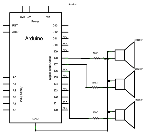
Schematic:
click the image to enlarge

Here's the main sketch:
SPlaying tones on Multiple outputs using the tone() function
This example shows how to use the tone() command to play different notes on multiple outputs.The tone() command works by taking over one of the Atmega's internal timers, setting it to the frequency you want, and using the timer to pulse an output pin. Since it's only using one timer, you can only play one note at a time. You can, however, play notes on multiple pins sequentially. To do this, you need to turn the timer off for one pin before moving on to the next.
Thanks to Greg Borenstein for clarifying this.
Circuit
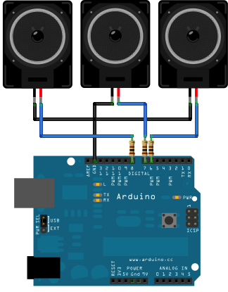
Schematic:
click the image to enlarge
Code
The sketch below plays a tone on each of the speakers in sequence, turning off the previous speaker first. Note that the duration of each tone is the same as the delay that follows it.Here's the main sketch:
/*
  Multiple tone player

 Plays multiple tones on multiple pins in sequence

 circuit:
 * 3 8-ohm speaker on digital pins 6, 7, and 11

 created 8 March 2010
 by Tom Igoe
 based on a snippet from Greg Borenstein

This example code is in the public domain.

 http://arduino.cc/en/Tutorial/Tone4

 */

void setup() {

}

void loop() {
   // turn off tone function for pin 11:
   noTone(11);
  // play a note on pin 6 for 200 ms:
  tone(6, 440, 200);
  delay(200);

  // turn off tone function for pin 6:
  noTone(6);
  // play a note on pin 7 for 500 ms:
  tone(7, 494, 500);
  delay(500);

  // turn off tone function for pin 7:
  noTone(7);
  // play a note on pin 11 for 500 ms:
  tone(11, 523, 300);
  delay(300);
}
fonte : http://arduino.cc/en/Tutorial/Tone4
tags : Arduino,SPlaying tones on Multiple outputs using the tone() function , Pedro Ernesto Scotton, Pedro Scotton, Starter Arduino
Simple keyboard using the tone() function
Examples > Digital I/O
 image developed using Fritzing. For more circuit examples, see the Fritzing project page
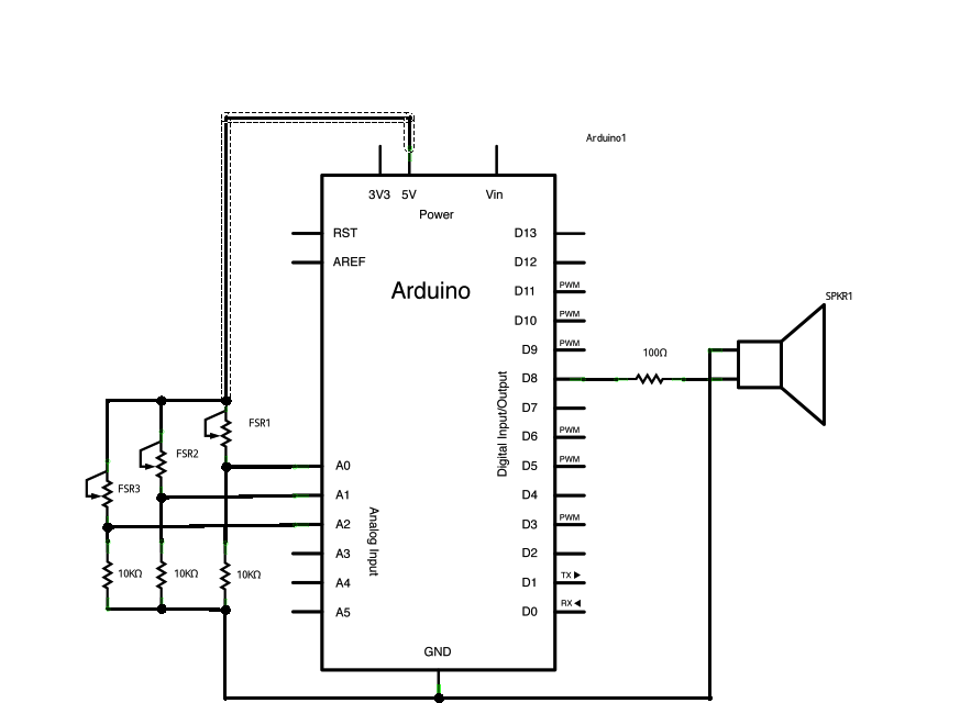
Schematic:
click the image to enlarge

The sketch uses an extra file, pitches.h. This file contains all the pitch values for typical notes. For example, NOTE_C4 is middle C. NOTE_FS4 is F sharp, and so forth. This note table was originally written by Brett Hagman, on whose work the tone() command was based. You may find it useful for whenever you want to make musical notes.
To make this file, click on the "new Tab" button in the upper right hand corner of the window. It looks like this:
 The paste in the following code:
Simple keyboard using the tone() function
This example shows how to use the tone() command to generate different pitches depending on which sensor is pressed.Circuit
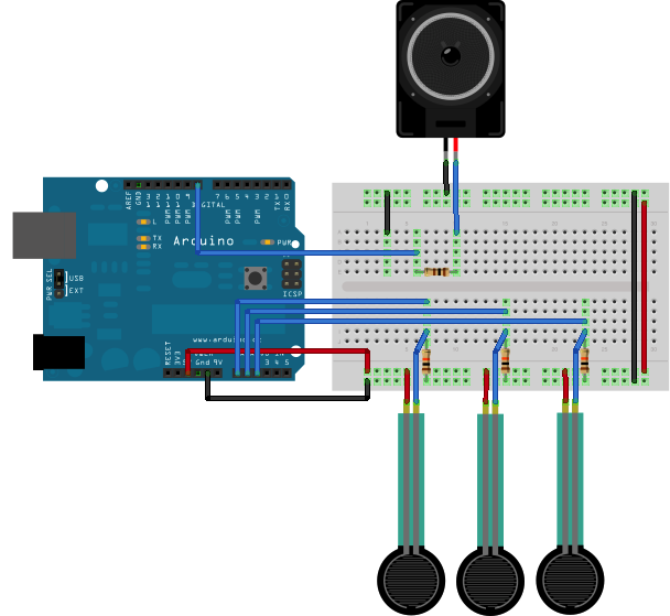
Schematic:
click the image to enlarge
Code
The sketch below reads three analog sensors. Each corresponds to a note value in an array of notes. IF any of the sensors is above a given threshold, the corresponding note is played.The sketch uses an extra file, pitches.h. This file contains all the pitch values for typical notes. For example, NOTE_C4 is middle C. NOTE_FS4 is F sharp, and so forth. This note table was originally written by Brett Hagman, on whose work the tone() command was based. You may find it useful for whenever you want to make musical notes.
To make this file, click on the "new Tab" button in the upper right hand corner of the window. It looks like this:
Pitch follower using the tone() function
Examples > Digital I/O
 image developed using Fritzing. For more circuit examples, see the Fritzing project page
Schematic:
click the image to enlarge

You'll need to get the actual range of your analog input for the mapping. In the circuit shown, the analog input value ranged from about 400 to about 1000. Change the values in the map() comand to match the range for your sensor.
The sketch is as follows:
Pitch follower using the tone() function
This example shows how to use the tone() command to generate a pitch that follows the values of an analog inputCircuit
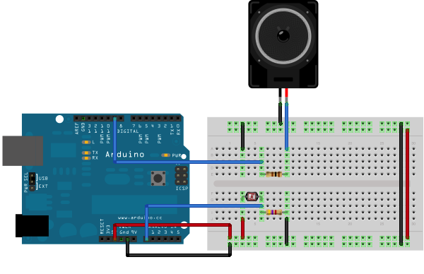
Schematic:
click the image to enlarge

Code
The code for this example is very simple. Just take an analog input and map its values to a range of audible pitches. Humans can hear from 20 - 20,000Hz, but 100 - 1000 usually works pretty well for this sketch.You'll need to get the actual range of your analog input for the mapping. In the circuit shown, the analog input value ranged from about 400 to about 1000. Change the values in the map() comand to match the range for your sensor.
The sketch is as follows:
/*
  Pitch follower

 Plays a pitch that changes based on a changing analog input

 circuit:
 * 8-ohm speaker on digital pin 8
 * photoresistor on analog 0 to 5V
 * 4.7K resistor on analog 0 to ground

 created 21 Jan 2010
 by Tom Igoe

This example code is in the public domain.

 http://arduino.cc/en/Tutorial/Tone2

 */


void setup() {
  // initialize serial communications (for debugging only):
  Serial.begin(9600);
}

void loop() {
  // read the sensor:
  int sensorReading = analogRead(0);
  // print the sensor reading so you know its range
  Serial.println(sensorReading);
  // map the pitch to the range of the analog input.
  // change the minimum and maximum input numbers below
  // depending on the range your sensor's giving:
  int thisPitch = map(sensorReading, 400, 1000, 100, 1000);

  // play the pitch:
  tone(8, thisPitch, 10);

}
Play Melody using the tone() function
Examples > Digital I/O
 image developed using Fritzing. For more circuit examples, see the Fritzing project page
Schematic:
click the image to enlarge

To make this file, click on the "new Tab" button in the upper right hand corner of the window. It looks like this:
The paste in the following code:
Play Melody using the tone() function
This example shows how to use the tone() command to generate notes. It plays a little melody you may have heard before.Circuit
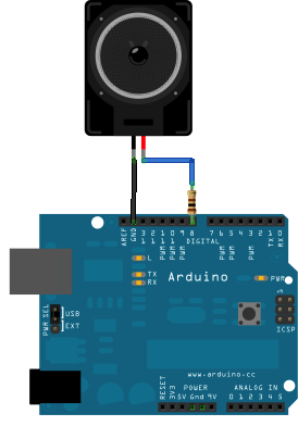
Schematic:
click the image to enlarge
Code
The code below uses an extra file, pitches.h. This file contains all the pitch values for typical notes. For example, NOTE_C4 is middle C. NOTE_FS4 is F sharp, and so forth. This note table was originally written by Brett Hagman, on whose work the tone() command was based. You may find it useful for whenever you want to make musical notes.To make this file, click on the "new Tab" button in the upper right hand corner of the window. It looks like this:
/*************************************************
 * Public Constants
 *************************************************/

#define NOTE_B0  31
#define NOTE_C1  33
#define NOTE_CS1 35
#define NOTE_D1  37
#define NOTE_DS1 39
#define NOTE_E1  41
#define NOTE_F1  44
#define NOTE_FS1 46
#define NOTE_G1  49
#define NOTE_GS1 52
#define NOTE_A1  55
#define NOTE_AS1 58
#define NOTE_B1  62
#define NOTE_C2  65
#define NOTE_CS2 69
#define NOTE_D2  73
#define NOTE_DS2 78
#define NOTE_E2  82
#define NOTE_F2  87
#define NOTE_FS2 93
#define NOTE_G2  98
#define NOTE_GS2 104
#define NOTE_A2  110
#define NOTE_AS2 117
#define NOTE_B2  123
#define NOTE_C3  131
#define NOTE_CS3 139
#define NOTE_D3  147
#define NOTE_DS3 156
#define NOTE_E3  165
#define NOTE_F3  175
#define NOTE_FS3 185
#define NOTE_G3  196
#define NOTE_GS3 208
#define NOTE_A3  220
#define NOTE_AS3 233
#define NOTE_B3  247
#define NOTE_C4  262
#define NOTE_CS4 277
#define NOTE_D4  294
#define NOTE_DS4 311
#define NOTE_E4  330
#define NOTE_F4  349
#define NOTE_FS4 370
#define NOTE_G4  392
#define NOTE_GS4 415
#define NOTE_A4  440
#define NOTE_AS4 466
#define NOTE_B4  494
#define NOTE_C5  523
#define NOTE_CS5 554
#define NOTE_D5  587
#define NOTE_DS5 622
#define NOTE_E5  659
#define NOTE_F5  698
#define NOTE_FS5 740
#define NOTE_G5  784
#define NOTE_GS5 831
#define NOTE_A5  880
#define NOTE_AS5 932
#define NOTE_B5  988
#define NOTE_C6  1047
#define NOTE_CS6 1109
#define NOTE_D6  1175
#define NOTE_DS6 1245
#define NOTE_E6  1319
#define NOTE_F6  1397
#define NOTE_FS6 1480
#define NOTE_G6  1568
#define NOTE_GS6 1661
#define NOTE_A6  1760
#define NOTE_AS6 1865
#define NOTE_B6  1976
#define NOTE_C7  2093
#define NOTE_CS7 2217
#define NOTE_D7  2349
#define NOTE_DS7 2489
#define NOTE_E7  2637
#define NOTE_F7  2794
#define NOTE_FS7 2960
#define NOTE_G7  3136
#define NOTE_GS7 3322
#define NOTE_A7  3520
#define NOTE_AS7 3729
#define NOTE_B7  3951
#define NOTE_C8  4186
#define NOTE_CS8 4435
#define NOTE_D8  4699
#define NOTE_DS8 4978
The main sketch is as follows:
/*
  Melody

 Plays a melody

 circuit:
 * 8-ohm speaker on digital pin 8

 created 21 Jan 2010
 by Tom Igoe

This example code is in the public domain.

 http://arduino.cc/en/Tutorial/Tone

 */
 #include "pitches.h"

// notes in the melody:
int melody[] = {
  NOTE_C4, NOTE_G3,NOTE_G3, NOTE_A3, NOTE_G3,0, NOTE_B3, NOTE_C4};

// note durations: 4 = quarter note, 8 = eighth note, etc.:
int noteDurations[] = {
  4, 8, 8, 4,4,4,4,4 };

void setup() {
  // iterate over the notes of the melody:
  for (int thisNote = 0; thisNote < 8; thisNote++) {

    // to calculate the note duration, take one second
    // divided by the note type.
    //e.g. quarter note = 1000 / 4, eighth note = 1000/8, etc.
    int noteDuration = 1000/noteDurations[thisNote];
    tone(8, melody[thisNote],noteDuration);

    // to distinguish the notes, set a minimum time between them.
    // the note's duration + 30% seems to work well:
    int pauseBetweenNotes = noteDuration * 1.30;
    delay(pauseBetweenNotes);
  }
}

void loop() {
  // no need to repeat the melody.
}
Debounce
Examples > Digital I/O
 image developed using Fritzing. For more circuit examples, see the Fritzing project page
Schematic:
click the image to enlarge

Debounce
This example demonstrates the use of a pushbutton as a switch: each time you press the button, the LED (or whatever) is turned on (if it's off) or off (if on). It also debounces the input, without which pressing the button once would appear to the code as multiple presses. Makes use of the millis() function to keep track of the time when the button is pressed.Circuit
Schematic:
click the image to enlarge
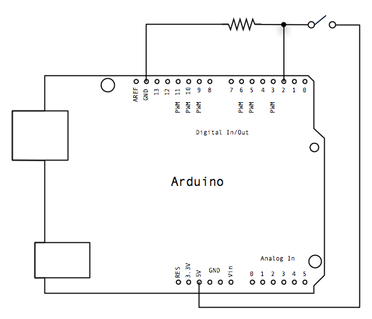
Code
The code below is based on Limor Fried's version of debounce, but the logic is inverted from her example. In her example, the switch returns LOW when closed, and HIGH when open. Here, the switch returns HIGH when pressed and LOW when not pressed./*
Debounce
Each time the input pin goes from LOW to HIGH (e.g. because of a push-button
press), the output pin is toggled from LOW to HIGH or HIGH to LOW. There's
a minimum delay between toggles to debounce the circuit (i.e. to ignore
noise).
The circuit:
* LED attached from pin 13 to ground
* pushbutton attached from pin 2 to +5V
* 10K resistor attached from pin 2 to ground
* Note: On most Arduino boards, there is already an LED on the board
connected to pin 13, so you don't need any extra components for this example.
created 21 November 2006
by David A. Mellis
modified 3 Jul 2009
by Limor Fried
This example code is in the public domain.
http://www.arduino.cc/en/Tutorial/Debounce
*/
// constants won't change. They're used here to
// set pin numbers:
const int buttonPin = 2; // the number of the pushbutton pin
const int ledPin = 13; // the number of the LED pin
// Variables will change:
int ledState = HIGH; // the current state of the output pin
int buttonState; // the current reading from the input pin
int lastButtonState = LOW; // the previous reading from the input pin
// the following variables are long's because the time, measured in miliseconds,
// will quickly become a bigger number than can be stored in an int.
long lastDebounceTime = 0; // the last time the output pin was toggled
long debounceDelay = 50; // the debounce time; increase if the output flickers
void setup() {
pinMode(buttonPin, INPUT);
pinMode(ledPin, OUTPUT);
}
void loop() {
// read the state of the switch into a local variable:
int reading = digitalRead(buttonPin);
// check to see if you just pressed the button
// (i.e. the input went from LOW to HIGH), and you've waited
// long enough since the last press to ignore any noise:
// If the switch changed, due to noise or pressing:
if (reading != lastButtonState) {
// reset the debouncing timer
lastDebounceTime = millis();
}
if ((millis() - lastDebounceTime) > debounceDelay) {
// whatever the reading is at, it's been there for longer
// than the debounce delay, so take it as the actual current state:
buttonState = reading;
}
// set the LED using the state of the button:
digitalWrite(ledPin, buttonState);
// save the reading. Next time through the loop,
// it'll be the lastButtonState:
lastButtonState = reading;
}
Assinar:
Postagens (Atom)